The US Bayonet-Knife, M4 (First Production 1944-45)
![]()
A standard production Bayonet-Knife, M4 as manufactured during the first production period 1944-45 (Specimen shown by Imperial Knife Company)
The leather gripped M4 Bayonet in recent years has become very collectible. In this article, I will show some of the variations in this bayonet, as well as some details from each of the World War 2 period makers. I would like to emphasize that this is not a comprehensive study of this bayonet, but rather a beginner's primer on the subject. All of the bayonets illustrated are from my personal reference collection, and therefore are very limited in scope. I am sure there are some details that I fail to mention, or that do not appear on specimens in my collection.
Historical Background
When the development of the Carbine, Caliber .30, M1 was begun in June, 1940 it was planned to be used as a replacement for the handgun, which was considered to be ineffective in the hands of most users beyond a range of 25 yards. It was also thought that such a carbine might replace the submachine gun for certain uses..
As such, the proposed characteristics of the new weapon did not list a requirement for a bayonet. The primary characteristics were to be light weight, reliability, and an effective range of about 300 yards.
After development and early production of the Carbine, it was recognized that many of the troops armed with the new weapon might at times have use for a knife since they lacked a bayonet. As the Knife, Trench, M3 was just then being formally adopted, it was directed that most soldiers armed with the Carbine were to be issued an M3 to both satisfy the general purpose need for a knife as well as possible use in close combat.
The using services soon began to request a bayonet for the Carbine. This was at first met with some resistance by the Ordnance Department as it was felt that the light barrel would not provide sufficient support under combat use. (Later tests and field use indeed found that typical bayonet training or combat use of the Carbine and the M4 bayonet would often result in some damage to the barrel or stud.)
In October of 1943 the Army Service Forces initiated development of a bayonet for the Carbine. Four models were developed for testing. The first three types tested clamped over the barrel just behind the front sight, using the wing nut and clamp assembly from the M8 grenade launcher. The T4 had a 7-inch spike blade similar to the British No. 4. The T5 had a similar blade but of a diamond cross section. The T6 had a 7-inch blade similar in configuration to the M3 trench knife.
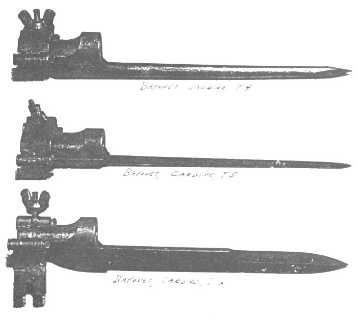
Photo of the T4, T5 and T6 test bayonets for the M1 Carbine.
This photo is from an Army publication titled Restricted Report and Photos of:
M3 Knife, T-4, T-5, T-6, T-8 Bayonets - M1 Bayonet and T-2 Bayonet
Although testing showed that the T4, T5 and T6 were adequate as bayonets, they lacked utility as knives, and this would necessitate many soldiers carrying both a bayonet and a knife. The T8 however would serve both functions and was considered the best design.
The T8 was an M3 trench knife that utilized a modified guard with a barrel ring and a butt plate with a T shaped cut and a single spring loaded catch to latch it to an extension of the front band. Testing showed that the single catch did not adequately secure the bayonet, and a second catch was added on the opposite side. This model was designated the T8E1.
Headquarters, Army Ground Forces in their report recommended that the T8E1 bayonet be "standardized and manufactured in lieu of the Knife, Trench, M3 inasmuch as the modification in no way detracts from its use as a knife, but instead enhances its value by making it a dual purpose weapon". The T8E1 as therefore adopted in May 1944 as the Bayonet-Knife, M4.
The 7 companies manufacturing the M3 Knife were given the new specifications and were instructed to convert to the M4 as soon as the new parts (guard and butt plate) were available. First deliveries began in late July and quantity production began in the following months. Final deliveries of the M3 trench knife were in August 1944.
Although quantity production of the M4 began during 1944, carbines fitted with the bayonet adapter did not reach combat troops until very late in the war. From available photographic evidence and veteran recollections, it appears very few, if any, bayonet-equipped carbines were used in combat operations in the European Theater. It is possible that some saw action on Okinawa, but if so, it was a small number.
However, the fact that the M4 saw little or no use as a bayonet in World War 2 does not mean that it was not used in combat zones during the war. Once production of the M3 knife ceased, the M4 became the substitute and was issued in place of the M3. So although the M4 saw little or no action as a bayonet, it was extensively issued and carried as a general-purpose belt knife.
Parts and Nomenclature

Parts diagram and stock number listing.
From Army Service Forces Catalog ORD 9 SNL B-8
List of All Pats of Bayonet, M1905, M1917, M1, and Bayonet-Knife, M4
dated 16 February 1945
Column 1 - Stock Number
Column 2 - Figure Number
Column 3 - Ordnance Part Number
Column 4 - Ordnance Drawing Number
Column 5 - Nomenclature
Column 6 - Quantity per Unit Assembly
Dimensions of the M4 are: (all dimensions are nominal and
may vary slightly)
Overall Length: 11 3/4 inches
Blade Length: 6 3/4 inches
Blade Width: 7/8 of an inch
Length of True Edge: 6 1/4 inch (will vary about 1/4 inch depending on maker)
Length of False Edge: 3 1/4 inches (will also vary according to maker)
Weight: 9 ounces
Grip Material: Leather Washers (number varies with maker depending on whether
they used the plastic spacers on the ends. Normally about 32 to 34 washers.
Just as a note - don't always depend on what is stated in the manuals. As an example, TM 9-2200 Small Arms Materiel and Associated Equipment of April 1949 on page 66 states about the Bayonet-Knife, M4: Length (over-all) 11 3/4 in. Length of Blade 10 3/4 in. (Leaving a 1-inch grip length.)
All metal was Parkerized, and the color will vary somewhat from maker to maker. In general, the finish ranges from a light to medium gray, and is rather smooth. It appears that most of the makers polished the blades prior to finishing, resulting in a very smooth, almost slick finish, especially when oiled. Camillus, on their worksheets, listed the blades as "glazed and parked", meaning that they polished the blades prior to Parkerizing the same as if they were to be blued.
Final sharpening of the blade was after the Parkerizing was done. This resulted in a bright "line of white" that can be seen if the blade is still in good condition. Later use, sharpening, rust and patina, etc. will often obscure this line. The Bayonet-Knife, M4 was sharpened to a higher degree than the Bayonet, M1 as its intended use was more as a knife than a bayonet.

The bright "line of white" sharpened line that can be seen on some M4 blades.
Darker, granular finishes almost always indicate a later refinish. Another indication of a refinish is worn grips with a high percent of blade finish. Following WW2 the standard refinishing method was to suspend the blade in a Parkerizing solution and paint the guard and butt as needed with a flat or low gloss black paint. This method was used as it was found to be too expensive to disassemble the bayonet, refinish the metal, and reassemble it. If the grips were in too bad a condition to allow continued use of the bayonet, the entire bayonet was scrapped.
Changes and Variations
As the M4 was produced in quantity for only about one year, it can be understood that there are few variations. There are variations in the grip that is actually the result of a changeover in production methods, and one official change was made in the catch retaining pins in the butt.
The M3 knife normally had a grip of stacked leather washers with 8 "square" grooves (that is, grooves with parallel sides). The grooves were made by either using leather washers of different diameters (#3 and #2 washers) or by cutting the grooves into a single diameter washer during the finishing process (called "hafting" in the industry). Close inspection can allow the collector to determine which version they have by observing whether the washers are all the same width or if the groove has been cut into the washers.
When the M4 was adopted the specifications called for 6 grooves rather than the 8 of the M3, although it may be that some very early M4s can be found with 8 grooves. An early specimen made by Kinfolks in my collection has six narrow square grooves spaced the same as the middle six had been on the M3, leaving more space on both ends than usual. This probably indicates very early production, about the time of the changeover from the M3 trench knife to the M4 bayonet. A photo is shown in the Kinfolks section.
The use of different size washers to create the grooves continued in some of the plants for some time. In January 1945 Major Arthur G. Snyder, an inspector from the Ordnance Department visited the Aerial plant and reported: "While the facility is setting up a machine for the grooving of the knife handle, they have a desire to continue to manufacture the present handle- stating it would result in the conservation of leather which would otherwise be discarded as scrap. It is said this present saving is due to the use of smaller washers to provide the handle grooves."
Most of the makers installed the grooving machine before they began making the M4, and the bulk of M4 production is found with 6 cut grooves. The square groove had proven to be subject to damage as the edges of the groove were not well supported, and the new specifications called for a somewhat shallower groove with a "V" shape. This became the common grip and is found on a high percentage of M4 production, although some makers used the square grooves on their early M4s.
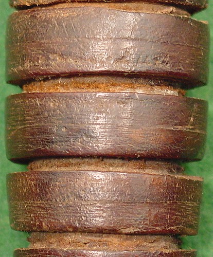
Square groove grip using two full width washers between each groove, and a different diameter (and apparently thickness) washer to create the grooves. Note that the surface of the groove washer is not clean and smooth as it would have been had it been created by a cutter.

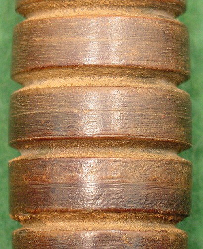
Square groove grip using all the same size washers with the square grooves cut into them. Note in second section from the bottom, there is one full washer in the middle and two partial sections of washers on each side where part of each washer was cut away. On the section below it, there is a full width and partial width washer. The bottom of the groove is smooth and clean where the cutter blade smoothed it.
Typical "V" groove grip used on most M4 production. The width and depth of the groove will vary slightly between makers. Most follow the pattern shown here with the V cut out of a single washer and the other washers being full width, although some seem to fall randomly on or between washers.
According to Frank Trzaska, the grips were assembled by first placing the blade in a fixture that held it firmly. The guard was slipped over the tang and into position. About three of the leather washers were slid over the tang, and a steel tool shaped something like a deep well socket was placed onto the washers and struck with a mallet to compress them. More washers were added and the process repeated until all of the washers were in place and compressed. The butt plate was then placed over the tang and peened in place. The washers soon swelled back and made the handle tight.

Note the bright line mark on the upper blade to the right, and the slight damage to the edges of the runout (backcut). I believe these may be the result of being held in the fixture during the grip assembly and tang peen as marks similar to this are found on most M4s. It should also be noted that the bright line is at about the same location as the mark left by the retaining springs in the M8A1 scabbard and may be the result of scabbard wear. However, I have seen this mark on blades that show no other trace of wear from the scabbard springs.
Some makers used brown plastic spacers at each end of the grip. I have not found a specification that required such use or the official reason for it. The general feeling among collectors is that it prevented moisture absorbed by the leather grip from coming in contact with the metal of the guard and butt, and therefore helped prevent rust. Specimens in my reference collection made by Camillus, Imperial, Pal, and Utica have these spacers. Very early production by these makers may not have used the spacers. I have not seen Aerial, Case, or Kinfolks made M4s with the spacers, but they may have used them late in production. Camillus states that they purchased the spacers from Beckwith Manufacturing, the supplier of the M8A1 scabbards for these bayonets, and it is likely that the other makers procured them from Beckwith also.
The only official change in the specification involved the pins that retained the catches in the butt plate. The bulk of the butt plate assemblies were manufactured on subcontract to the M4 makers by the Standard Products Company of Port Clinton, Ohio. Standard Products, well known for their manufacture of the M1 Carbine and many other Ordnance products during WW2 had been a pre-war supplier of automobile trim and accessories. As the production of the butt plate assembly was something that most of the knife makers were not set up to do, it was decided to subcontract the entire production of the plate to Standard Products and supply the plate assemblies to the makers as Government Free Issue. Their production is marked by an intertwined SP logo. One or more numbers are usually found on the face of the plate, and it is not known for certain what the numbers mean. The current "best guess" seems to be that they are batch or heat treat numbers.
It appears that Standard Products were at times unable to deliver sufficient numbers of the plate assemblies to allow the various makers to meet their obligations. The previously mentioned report of Major Snyder at the Aerial plant stated: "Upon entering this plant a conference was held with the owner, Mr. Fred Jaeger and the Manager, Mr. Ray Schuck. Up to 20 January the plant had been working day and night in order to meet a 10,000 piece January schedule. 7,500 blades had been processed. At 2 PM on the day of this visit the plant ran out of plate assemblies and had to close that part of the plant. It developed that 4,000 plates had been received and assembled at 2 PM on January 20. A facility call to the Standard Products Company (Detroit office) brought out the information that 1,000 more were "on the way". The writer advised the facility to request Standard Products Company to contact immediately their Ordnance District and the Hand Arms and Equipment Branch, Office, Chief of Ordnance, in an effort to reconcile a 10,000 knife schedule and a 4,000 plate delivery up to 20 January. This was done immediately."
This problem may be part of the reason that another company became involved in producing the plate assemblies. The Hemphill Company of Pawtucket, Rhode Island, a pre-war manufacturer of knitting machines for men's hosiery produced a much smaller number than Standard Products. During the war, they produced M1 Carbine parts, sights, and other ordnance materials, earning the factory a government award at the end of the war. It appears that the butt plates supplied by Hemphill were used mostly if not totally by the Imperial Knife Company. Hemphill used an H in a shield for a logo on their production.
First production of the butt plate used slightly tapered catch retainer pins, which were driven tightly into the plate. This allowed the pins to be driven back out for replacement of the catches if this became necessary. It appears that the pins sometimes could loosen and fall out, and in February 1945 a straight pin that was staked in place replaced the tapered pin. From that point, the butt was considered an assembly and it was not contemplated that parts would be stocked or repairs made. About 1,400,000 of the first type butt plate were produced by Standard Products. Since SP were the only makers at the time, this dates a bayonet as pre- or post- February 1945 fairly accurately. I have never seen a first type butt made by Hemphill, but I have a very small sampling to go by. I believe Hemphill did not get into production until after the second type plate had been adopted.
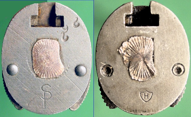
Left: First Type Butt Plate by Standard Products
Right: Second Type Butt Plate by Hemphill Company
In the latter part of 1944, the Isthmian Metals Inc. of Boston supplied Butt Plates manufactured from a powdered metal product. These plates were made in two pieces and copper brazed together. A series of tests were done at Watertown Arsenal using plates of regular manufacture as controls. Test results indicated that the plates were of a uniform high quality and were essentially equal in quality to the plates manufactured of standard steels. Unfortunately the test report does not make it clear why the material was being tested, but it can be assumed that the material would have been either cheaper, more readily obtainable or of more consistent quality. The war ended and production was cancelled before the final test reports were filed.
There is another detail that varies somewhat by maker, that being the design of the peen that holds the plate onto the tang. Some of the makers peened the tang on the M3 knife while others used a crosspin through the plate and tang. When the M4 came out, all the makers but one used what collector's call a "starburst" peen, with grooves radiating out from the center of the tang. Case used a distinctive semi-cylindrical strike. In the photos of each maker that follow, I show the peen mark on the base. The peens are slightly different from maker to maker, and sometimes a reasonable guess can be made as to the maker of a bayonet by the design of the starburst.
Production
Most of us give very little thought to the problems faced during production of an item such as the M4 bayonet. A very difficult balance had to be kept between demand, materials, and production capacity, even for an item as simple as this bayonet.
Demand: The Army Supply Programs attempted to predict how many bayonets would be needed to fill requirements as much as a year in advance. Obviously this was just an estimate, and the numbers often had to be changed during the year. This caused serious difficulties in assigning contract amounts and maintaining an adequate flow of the item into the supply chain.
For instance, initial requirements for 1944 were set at 776,000 and 737,697 in 1945, remembering that the M4 was considered a replacement for the M3 trench knife and issued as such. By late 1944 the 1945 requirements were raised to 1,747,064. In March, the production requirements for the Bayonet-Knife, M4 with Scabbard, M8A1 were changed to 1,960,002 and a further 803,009 in 1946. The defeat of Germany in May 1945 reduced the requirements by 832,897 for 1945 and 1946. Accordingly, only four companies were selected to continue deliveries through 1945 (Aerial, Imperial, Kinfolks, and Utica) and their monthly rates were greatly reduced.
It can easily be seen that changes of this nature made it very hard to maintain a smooth flow of product into the supply chain, and there were times when cancellations went out only to be replaced by emergency orders within a few weeks.
Materials: Due to the tremendous demand for steel from a wide variety of industries in wartime, it was often very difficult to obtain the steel for blades, guards and butt plates in a timely manner. In most cases, the bayonet maker only made the blade, obtaining the guards on subcontract and the butt plate from the primary supplier, Standard Products. This meant that they had to depend on these suppliers, as well as the steel supplier for the blade blanks, to make deliveries in a timely manner.
With the changes in requirements, and the demand for steel in other products, it was often difficult for these suppliers to provide the materials when needed. A committee, the Bayonet Industry Integration Committee was formed and aided the Ordnance Office in the elimination of bottlenecks. They especially worked with steel suppliers, and shifted materials from one plant to another to relieve shortages and avoid shutdowns in production.
Production Capacity: Although there was sufficient total production capacity to meet the requirements for most edged weapons, a serious problem continued throughout the war in the allocation of that capacity to specific requirements.
There were two situations that had to be balanced to make the best use of plant resources. The first was the specific product being made. There was so much demand for all sorts of edged weapons and tools that most makers would shift from one to another as demand fluctuated. That is, the maker would produce bayonets, or pocketknives, or sheath knives as needed. But if there was a sudden need for M4 bayonets, the company might be tied up in making Navy Mark 2 knifes and not have enough capacity to make both at the same time.
The second was manpower. Many plants were forced to lay off workers when contracts were cut back or completed. These workers usually had no problem in quickly finding other employment in a wartime economy, and when the company received new contracts and tried to recall these skilled workers, many of them were no longer available. It was to the benefit of both the plant and the Ordnance Department to try to keep the workforce stable by maintaining an even flow of product.
It was a major accomplishment for all concerned that in most circumstances the bayonets were available when and where they were needed and there were no major shortages during the war.
WE WILL BREAK HERE FOR THE FIRST MONTH - REMAINDER WILL BE BAYONET POINTS #17 NEXT MONTH.
All of the above reports referred to and the books are available on our Books For Sale and or Documents page.